Day by day the price of solar panels falls gradually. But still, installation of a complete off grid solar system is costly. That’s why I decided to write this guide on how to get all the components of your solar system separately and assemble it all by yourself.
If you have decided to install a solar panel system to cover your home power needs, then this tutorial is for you.
I have tried my best to guide you step by step, from buying different components to wiring everything by yourself.
You have to know some basic electrical and math for designing the entire system. I have also attached links of my other instructions to make the charge controller and energy meter.
For an off grid solar system you need four basic components
- Solar Panel (PV Panel)
- Charge Controller
- Inverter
- Battery
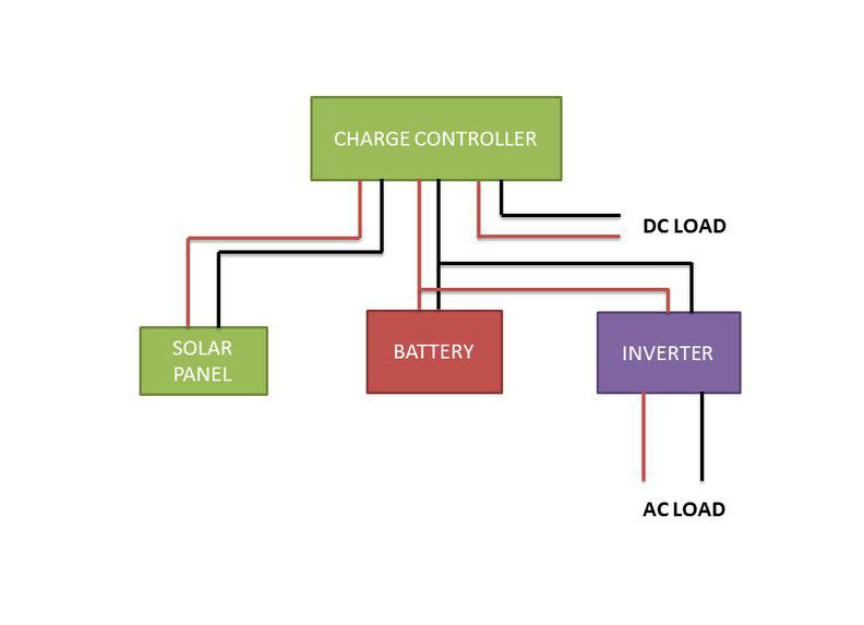
Here’s how all the pieces fit together:
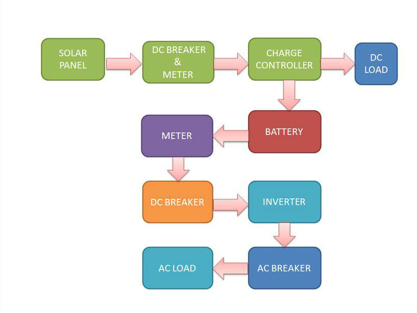
How the solar system fits together
Besides the above components you need a few more things like Copper Wire, MC4 Connector, breaker, meter and fuses, etc.
In the next few steps I will explain in details how you can choose the above components according to your requirement.
Note: In the pictures I have shown a big solar panel of 255W @ 24V, two batteries of 12V @ 100Ah each, 30A @ 12/24V PWM solar charge controller and a 1600 VA pure sine wave inverter. But during the calculation I have taken a smaller solar system example for better understanding.
Step 1: Calculate Your Load
Before choosing the components you have to calculate your power load, how much time it will run, etc. It is very simple to calculate if you know basic math.
- Decide what appliances (light,fan,tv etc ) you want to run and how much time (hours).
- See the specification chart in your appliances for power rating.
- Calculate the Watt Hour which is equal to the product of the power rating of your appliances and run time (hours).Load Calculation Example:Lets you want to run a 11W compact fluorescent lamp (CFL) for 5 hours from a solar panel, then the watt hour is equal to:
Watt Hour = 11W x 5 hr = 55
- Calculate the total Watt Hour: Just as with the CFL we’ll now calculate the watt hour for all the appliances and add them together.Example:CFL = 11W x 5 hr = 55Fan = 50 W x 3hr = 150TV = 80W x 2hr = 160
Total Watt Hours = 55+150+160 = 365
Now the load calculation is over, next thing is to choose the right components to match your load requirement.
If you are not interested in doing the above maths then use a load calculator for this calculation. There are many such load calculators available in the internet, for example this Off Grid Load Calculator.
Step 2: Battery Selection
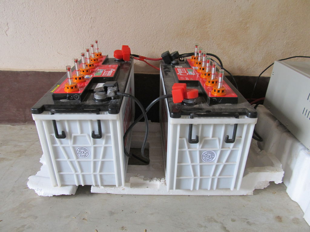
The batteries I use for my solar system
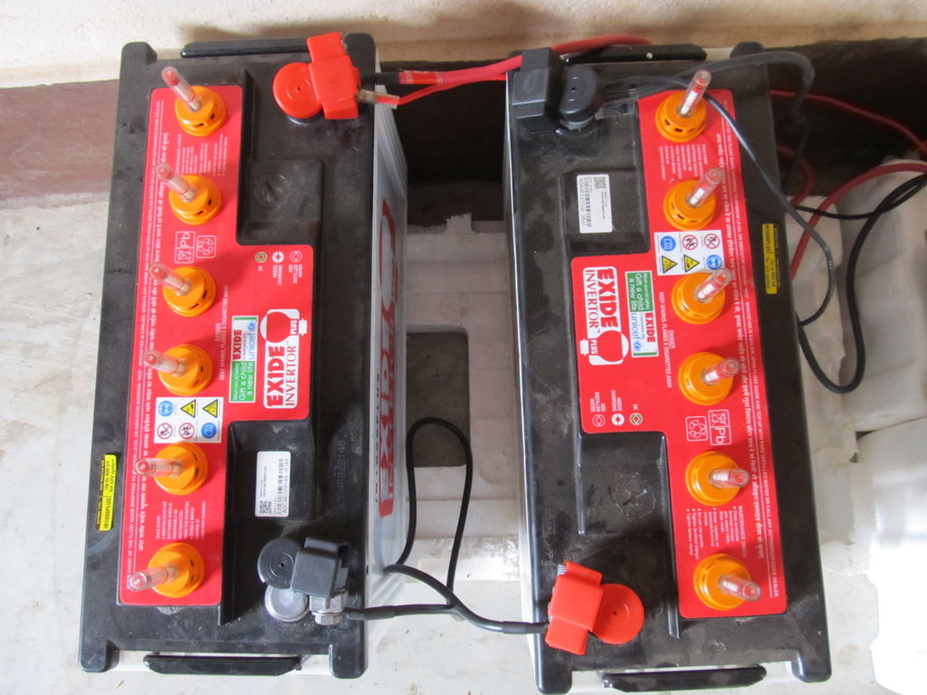
Top view of the batteries
The output from the solar panel is dc power. This power is generated during day time only. So if you want to run a dc load during day time then it seems to be very easy. But doing this is not a good decision because…
- Most of the appliances need a constant rated voltage to run efficiently. Solar panel voltage is not constant, it varies according to the sun light.
- If you want to run the appliances during the night then it is impossible.
The above problem is solved by using a battery to store the solar power during the day and use it according to your choice. It will provide constant source of stable, reliable power.
Video: Battery Selection for Solar Power
There are various kind of batteries. Car and bike batteries are designed for supplying short bursts of high current and then be recharged and are not designed for a deep discharge. But the solar battery is a deep-cycle lead-acid battery that allows for partial discharge and allows for deep slow discharge. Lead acid tubular batteries are perfect for a solar system.
Ni-MH batteries and Li-Ion batteries are also used many small power application.
Video: Battery Capacity and Efficiency
Note: Before going to choose the components decide your system voltage, 12/24 V or 48 V. The higher the voltage, the lesser the current and the lesser the copper loss will be in the conductor. This will also reduce your conductor size. Most of the small home solar systems will have 12 V or 24 V.
In this project I’ve selected the 12 V system.
Rating of Battery:
Batteries capacity are rated in term of Ampere Hour.
Power = Voltage X Current
Watt Hour = Voltage (Volts) x Current (Amperes) x Time (Hours)
Battery Voltage = 12V ( as our system is 12V)
Battery capacity = Load / Voltage = 365/12 = 30.42 Ah
But batteries are not 100% efficient, assuming 80% efficiency
Capacity = 30.42/0.8 = 38.02 Ah
By taking some margin you can select a 40Ah deep cycle lead acid battery.
Step 3: Solar Panel Selection
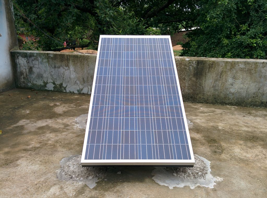
A big 255W solar panel @ 24V
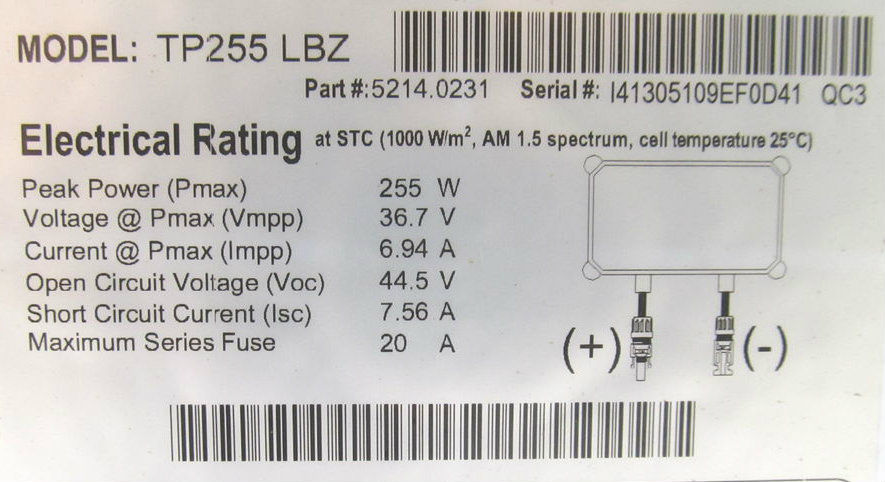
Solar panel ratings for the 255W solar panel
The Solar Panel converts the sunlight into electricity as direct current (DC). These panels are typically categorized as mono crystalline or poly crystalline. Mono crystalline are costlier and more efficient than poly crystalline panels.
Solar panels are generally rated under standard test conditions (STC): irradiance of 1,000 W/m², solar spectrum of AM 1.5 and module temperature at 25°C.
Rating of Solar Panel:
The solar panel size should be selected in such way that it will charge the battery fully in one sunny day.
During the 12hr day time the sunlight is not uniform, and it also differ according to your location on the globe. So we can assume 4 hours of effective sunlight which will generate the rated power.
So total power output of Panels = 12V x 40Ah = 480Wh
Power to be generated per hour = 480 / 4 = 120W
By taking some margin you can choose a 125 W, 12v solar panel.
Step 4: Charge Controller Selection
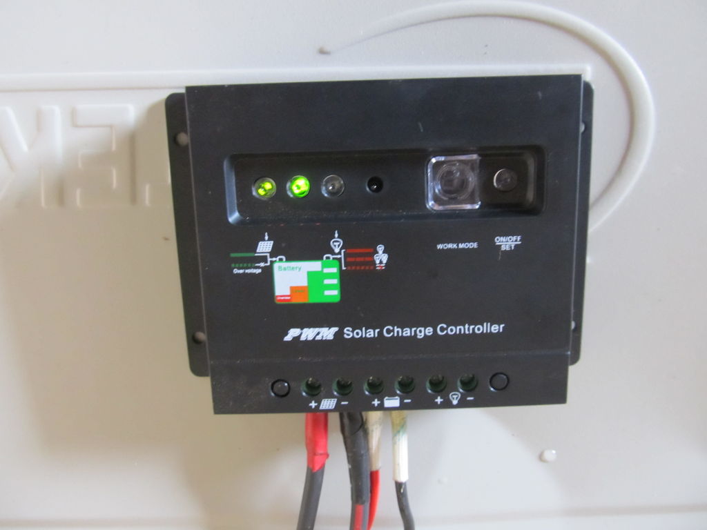
An example charge controller
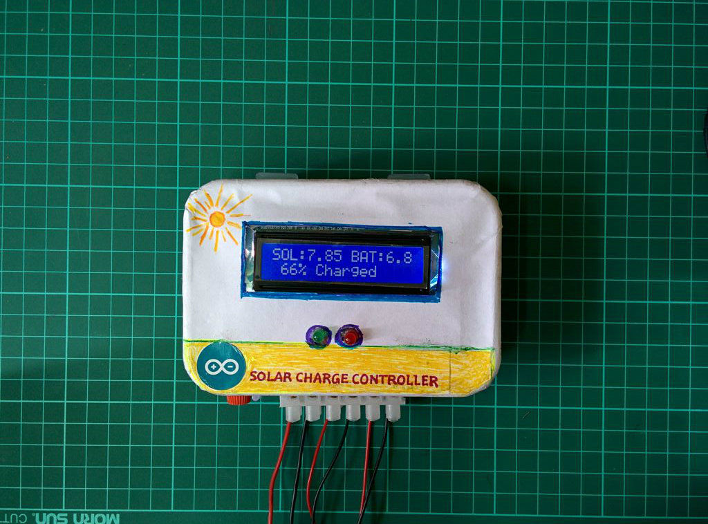
Another charge controller
A solar charge controller is a device which is placed between a solar panel and a battery. It regulates the voltage and current coming from your solar panels. It is used to maintain the proper charging voltage on the batteries. As the input voltage from the solar panel rises, the charge controller regulates the charge to the batteries preventing any over charging.
Usually, the solar power systems uses 12 volt batteries, however solar panels can deliver far more voltage than is required to charge the batteries.
By, in essence, converting the excess voltage into amps, the charge voltage can be kept at an optimal level while the time required to fully charge the batteries is reduced. This allows the solar power system to operate optimally at all times.
Types of Charge Controllers:
- ON OFF
- PWM
- MPPT
Try to avoid the ON/OFF charge controller as it is the least efficient.
Among the 3 charge controllers MPPT have the highest efficiency but it is also costly. So you can use either PWM or MPPT.
Rating of Charge Controller:
Since our system is rated at 12V, the charge controller is also 12V.
Current rating = Power output of Panels / Voltage = 125 W / 12V = 10.4 A
So choose a Charge Controller of 12 V and more than 10.4 A.
If you like to reduce your system cost you can make your own PWM charge controller. For step by step instructions you can see my instructable on building a PWM Charge Controller.
You may also like my new 3.0 design of an Arduino MPPT Solar Charge Controller.
Step 5: Inverter Selection
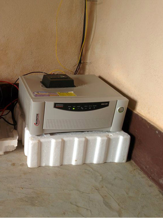
My 1600 VA pure sine wave inverter
Video: Why We Need an Inverter in a Solar PV System
Solar panels (PV) receive the sun’s rays and convert them into electricity called direct current (DC). DC is then converted into alternating current (AC) through a device called an Inverter. AC electricity flows through every outlet of your home, powering the appliances.
Inverter Types
- Square Wave
- Modified Sine Wave
- Pure Sine Wave
Square wave inverters are the cheapest but not suitable for all appliances. Modified Sine Wave output is also not suitable for certain appliances, particularly those with capacitive and electromagnetic devices such as: a fridge, microwave oven and most kinds of motors. Typically modified sine wave inverters work at lower efficiency than pure sine wave inverters.
So in my opinion choose a pure sine wave inverter.
It may be grid tie or stand alone. In our case it is obviously stand alone and completely off-the-grid.
Rating of Inverter:
The power rating should be equal or more than the total load in watt at any instant.
In our case the maximum load at any instant = Tv (50W) + Fan (80W) + CFL (11W) = 141W
By taking some margin we can choose a 200W inverter.
As our system is 12V we have to select a 12V DC to 230V/50Hz or 110V/60Hz AC pure sine wave inverter.
Note: Appliances like fridge, hair drier, vacuum cleaner, washing machine, etc. likely have a starting power consumption several times greater than their normal working power (typically this is caused by electric motors or capacitors in such appliances). This should be taken into account when choosing the right size of inverter.
Step 6: Mounting the Solar Panel
After designing the solar system, buy all the components with appropriate rating as per the previous steps.
Now it is time to mount the solar panel. First choose a suitable location on the roof top, or on the ground, where there is no obstruction of sunlight.
Prepare the mounting stand: You can make it by your own or buy one. In my case I have taken the drawing from the solar panel company and made it at a near by welding shop. The tilt of the stand is nearly equal to the latitude angle of your location.
The stand for my big solar panel
I made a small wooden mounting stand for my 10 Watt solar panel. I have attached the pictures, so that any one can make it easily.

The DIY stand for my 10 watt solar panel
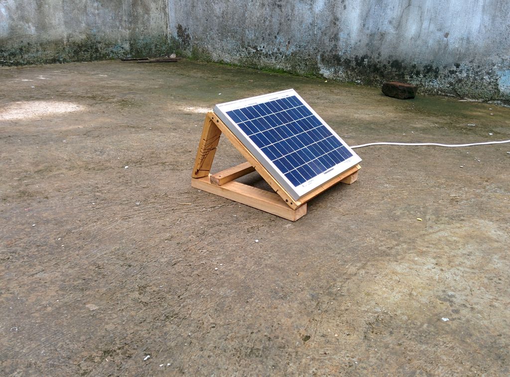
My 10 watt solar panel mounted on the stand
Tilting : To get the most from solar panels, you need to point them in the direction that captures the maximum sun light, i.e. south if you’re in the northern hemisphere or north if you’re in the southern hemisphere. You also have to optimize the angle relative to the ground. Use one of these formulas to find the best angle from the horizontal at which the panel should be tilted:
If your latitude is below 25°, use the latitude times 0.87.
If your latitude is between 25° and 50°, use the latitude, times 0.76, plus 3.1 degrees.
For more details on tilting click here
First, place the stand in such a way that the face is directed towards south (or north if you’re in the southern hemisphere. Mark the leg position over the roof.
To get the south / north direction use this compass android app (or even better, a real, physical compass!)
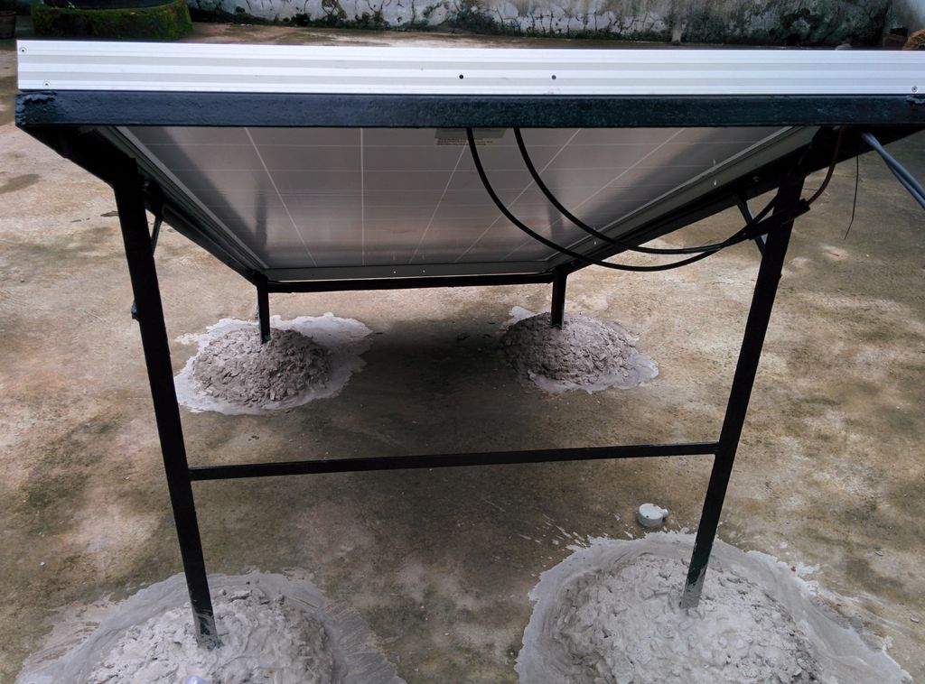
I decided to secure my 255W solar panel mount on my roof with concrete. I roughened up the surface at each leg of the stand by using a sharp object. I made around a 1 square feet size rough surface on the roof at each leg. This is helpful for perfecting the bonding between the roof and concrete.
Prepare concrete mix: Take cement and stones with 1:3 ratio then add water to make a thick mix. Pour concrete mix at each leg of the stand. I made a heap shape concrete mix to give maximum strength.
(You can of course secure it into place using other methods than concrete, this is just an example of a solution for my specific situation)
Mount the panels to the stand: At the back sides the solar panel have inbuilt holes for mounting. Match the solar panel holes with the stand/platform holes and screw them together.
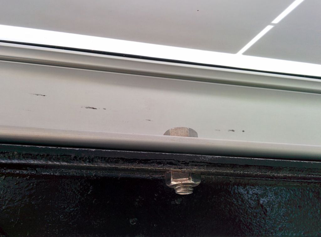
Mounting the solar panel
Wire the solar panel: At the back sides of the solar panel there is a small junction box with positive and negative sign for polarity. In a large size solar panel this junction box have terminal wires with MC4 connector but for small size panels you have to connect the junction box with external wires. Always try to use red and black wire for the positive and negative terminal connection. If there is provision for earth wire the use a green wire for wiring this.
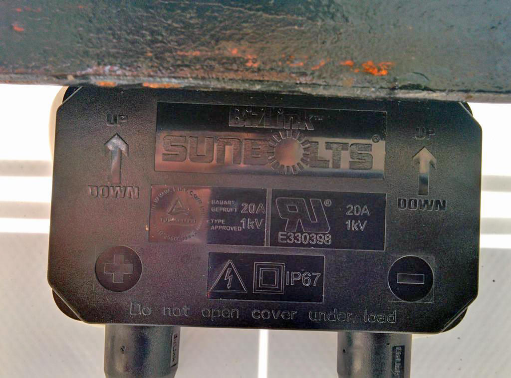
The junction box
Step 7: Series and Parallel Connection
After calculating the battery capacity and solar panel rating you have to wire them. In many cases the calculated solar panel size or battery is not readily available in the form of a single unit in the market. So you have to add a small solar panel or batteries to match your system requirement. To match the required voltage and current rating we have to use series and parallel connections.
1. Series Connection:
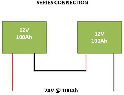
To wire any device in series you must connect the positive terminal of one device to the negative terminal of the next device. The device in our case may be solar panel or battery.
In series connection the individual voltages of each device is additive.
Example:
Lets say 4 12V batteries are connected in series, then the combination will produce 12 + 12 + 12 + 12 = 48 volts.
In series combination the current or amperage is same.
So if these devices were batteries and each battery had a rating of 12 Volts and 100 Ah then the total value of this series circuit would be 48 Volt, 100Ah. If they were solar panels and each solar panel had a rating of 17 volts (Osc voltage) and were rated at 5 amps each then the total circuit value would be 68 volts, 5 amps.
2. Parallel Connection:
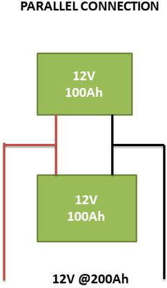
Parallel Connection
In parallel connection you must connect the positive terminal of the first device to the positive terminal of the next device and negative terminal of the first device to the negative terminal of the next device.
In parallel connection the voltage is remain same but the current rating of the circuit is the sum of all the devices.
Example:
Lets say two batteries of 12v, 100Ah are connected in parallel – then the system voltage remains 12 volts but the current rating is 100 + 100 = 200Ah. Similarly if two solar panels of 17V and 5 amps are connected in parallel then the system will produce 17 Volts, 10 amps.
Step 8: Inverter and Battery Stand
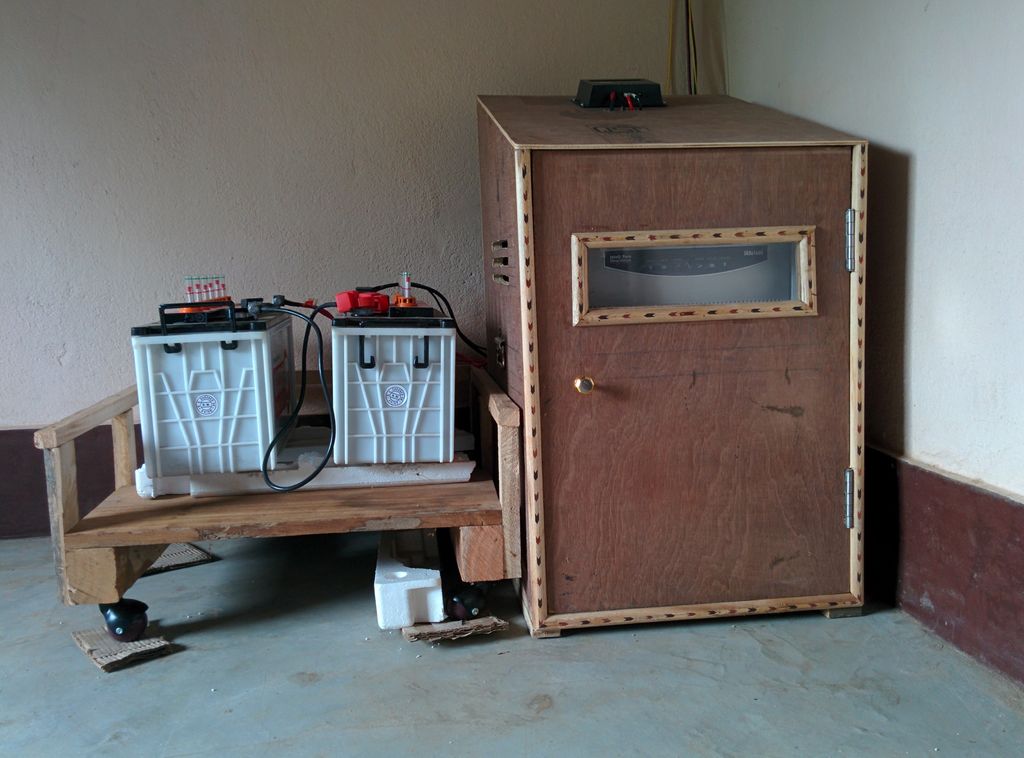
The battery and inverter stand that I built
I made the above inverter and battery stand with the help of a carpenter. The design idea I got from this instructable. The design was really helpful to me.
At the back side I made a big circular hole just behind the inverter fan for fresh air suction from the outside. Later I covered the hole with plastic wire mesh. A few small holes are also made for inserting the wires from the solar panel, charge controller and inverter to the battery and AC output to the appliances. At both sides 3 horizontal holes are provided for sufficient ventilation. A glass window is provided at the front side to view the different led indications on the inverter.
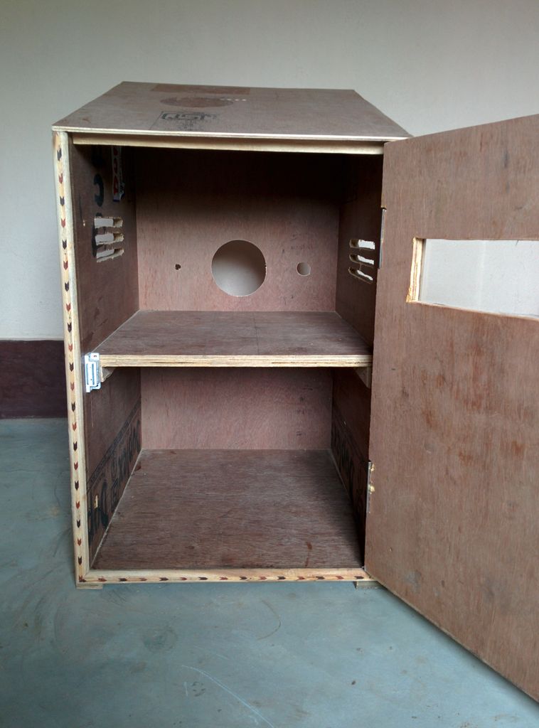
Inside view of the inverter stand
In the inclined plane of the inverter stand I have mounted the charge controller. In the future I will also install my own DIY energy meter.
Step 9: Wiring
How to wire the system
The first component we are going to wire is the Charge Controller. At the bottom of the Charge Controller there are 3 signs in my charge controller. The first one from the left is for the connection of the Solar Panel having positive (+) and negative (-) signs. The second one with plus (+) and minus (-) signs is for the Battery connection and the last one for the direct DC load connection like DC lights.
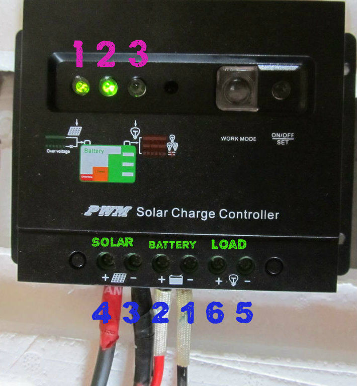
Closeup of the charge controller wiring
Wiring of the charge controller
As per the charge controller manual always connect the Charge Controller to the Battery first because this allows the Charge Controller to get calibrated to whether it is 12V or 24V system. Connect the red (+) and black (-) wire from the battery bank to the charge controller.
Note: First connect the black / negative wire from the battery to the charge controller’s negative terminal, then connect the positive wire.
After connecting the battery with the charge controller you can see the Charge Controller indicator led lights up to indicate the battery level.
After connecting this, inverter terminals for battery charging is connected to corresponding positive and negative terminals of the battery.
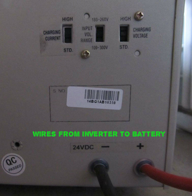
Inverter wiring
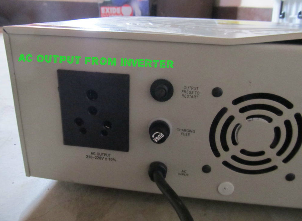
Inverter AC output
Now you have to connect the solar panel to the charge controller. At the back side of the Solar Panel there is a small junction box with 2 connected wires with positive(+) and negative (-) sign. The terminal wires are normally smaller in length.
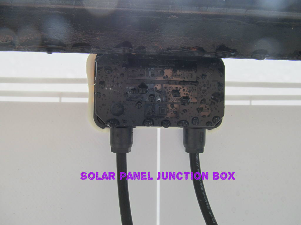
Solar panel junction box wiring
To connect the wire to the charge controller you need a special type of connector which is commonly known as MC4 connector. See the picture below. After connecting the solar panel to the charge controller the green led indicator will light up if sunlight is present.
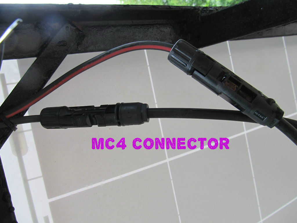
An MC4 connector
Note: Always connect the Solar Panel to the Charge Controller while facing the Panel away from the sun or you may cover the panel with a dark material to avoid sudden high voltage coming from the solar panel to the Charge Controller which may damage it.
Safety: It is important to note that we are dealing with DC current. So the positive (+) is to be connected to positive (+) and negative (-) with negative (-) from Solar Panel to Charge Controller. If it gets mixed up, the equipment can break and may catch fire. So you need to be extremely careful when connecting these wires. It is recommended to use 2 color wires i.e. red color for positive (+) and black color for negative (-). If you don’t have red and black wire you may wrap red and black tape at the terminals.
Connect the DC load or DC light as the final step.
Additional Protection: Though charge controller and inverter have inbuilt fuses for protection, you can put switches and fuses in the following places for additional protection and isolation.
- In between solar panel and charge controller
- In between charge controller and battery bank
- In between battery and inverter
After wiring all components the off-grid solar system is ready for use.
Metering and Data logging:
If you are interested to know how much energy is produced by your solar panel or how much energy being consumed by your appliances you have to use energy meters.
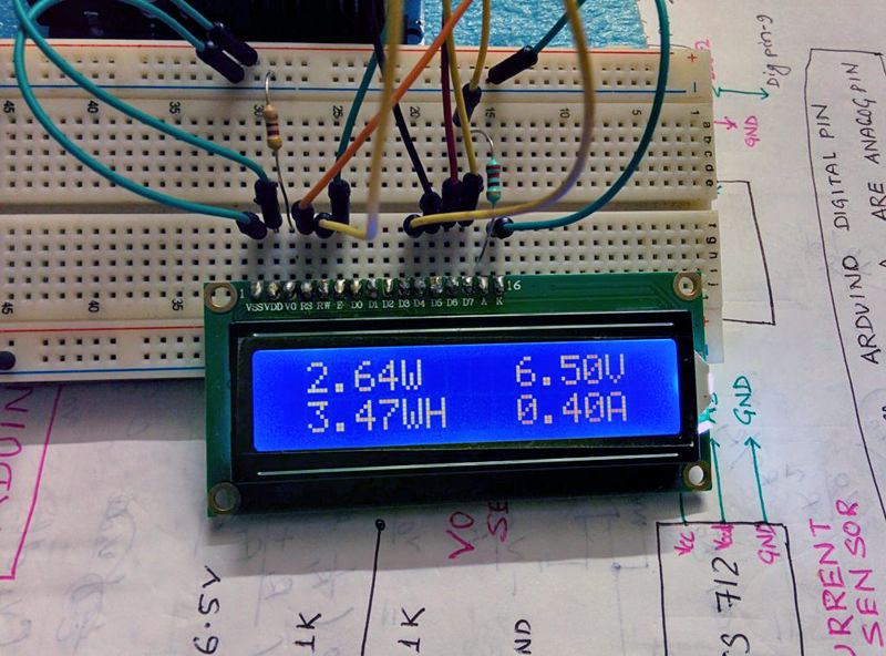
My DIY energy meter
Besides this you can monitor the different parameters in your off grid solar system by remote data logging
For a DIY based energy meter you can see my instructable on building an energy meter which have both metering and data logging capability.
Thank you for reading my instructions!
License: CC BY-NC-SA 2.5